Hydraulics, Brakes and Steering
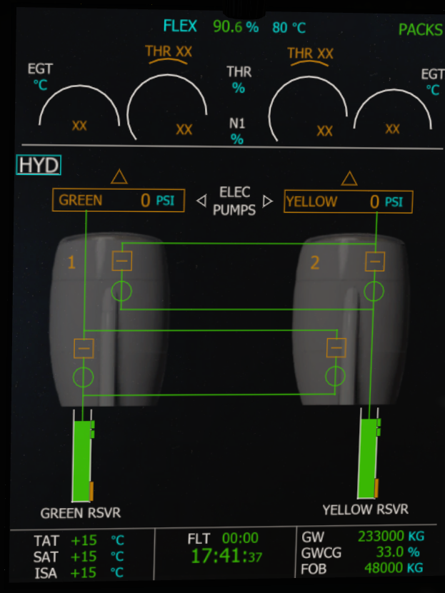
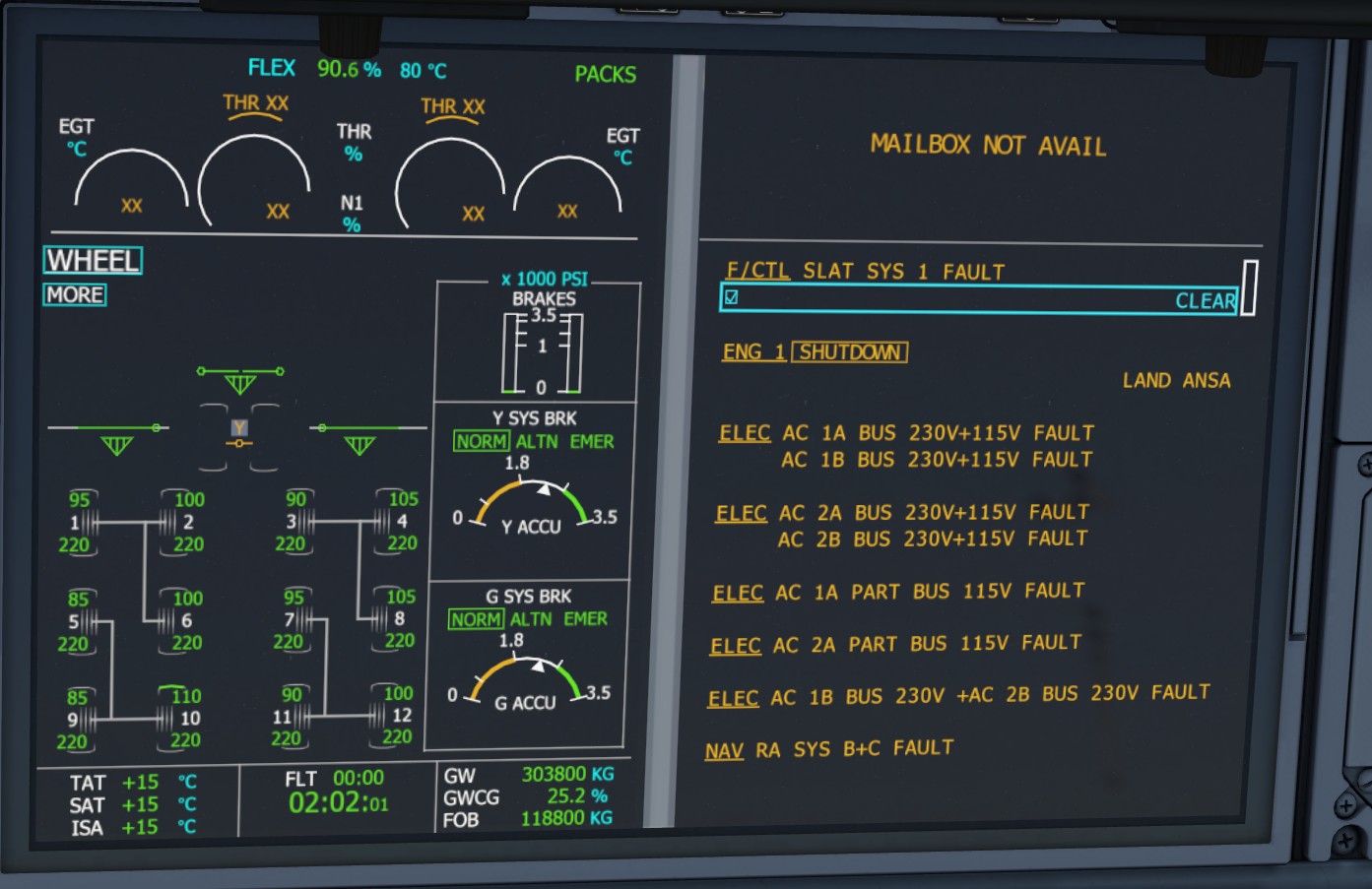
Green and Yellow hydraulic pressure is treated as an operational dependency, with engine-driven pressure, electric pumps, RAT recovery, low-pressure cautions, normal and alternate braking, nose-wheel steering and a consumable Yellow-system brake accumulator.
What It Models
Independent Green and Yellow pressure, pump logic, dual-system loss, RAT recovery, brake source switching and parking-brake accumulator pressure.
What You Will See
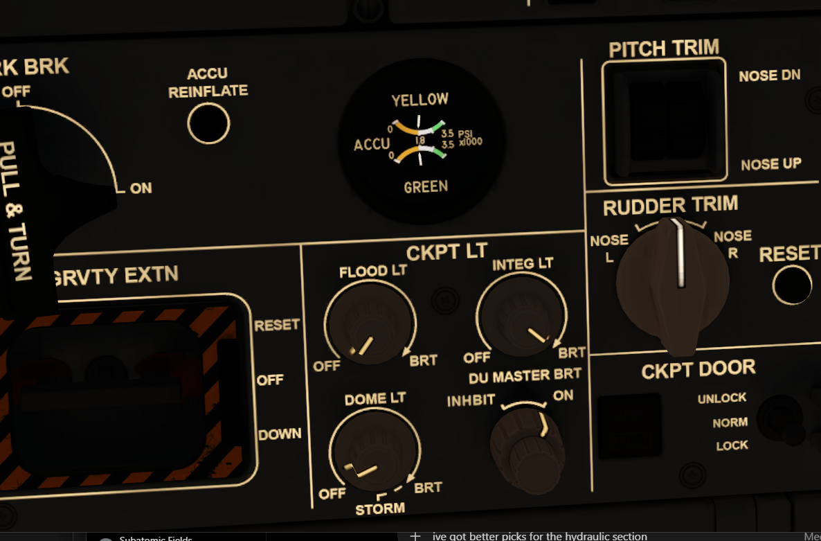
HYD cautions, reduced braking, accumulator depletion, amber parking-brake indications and loss of powered steering.
Normal Braking
Normal braking and autobrake use Green hydraulic pressure. With Green pressure and anti-skid available, the aircraft retains its normal stopping capability.
Alternate Braking
Loss of the normal braking path transfers braking to the Yellow hydraulic system. Further Yellow-system or anti-skid failures reduce the remaining capability.
Emergency Accumulator Braking
The Yellow-system accumulator provides limited stored braking pressure when the main hydraulic supplies are unavailable. Repeated applications consume that pressure until braking is no longer effective.
Flight Controls and Computer Logic
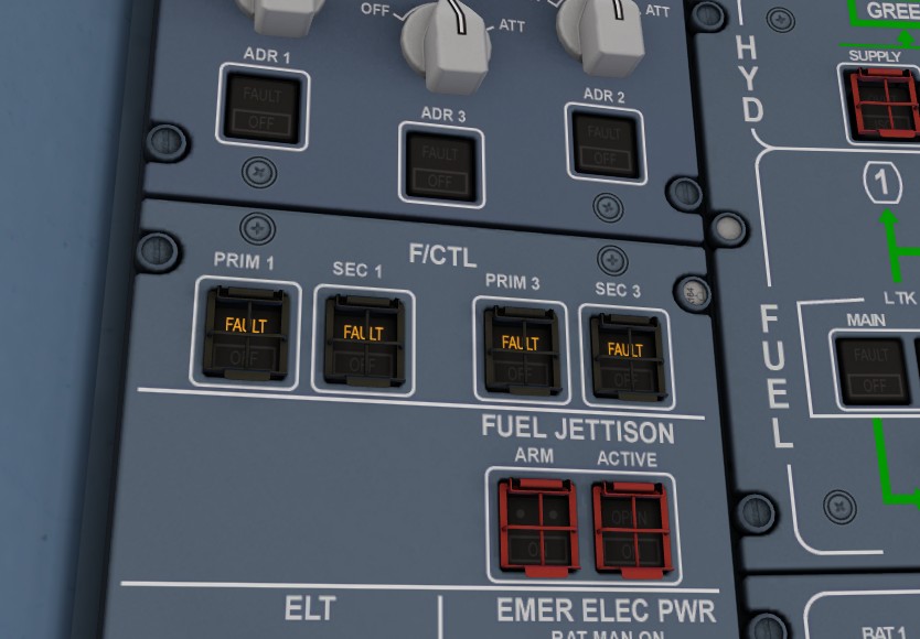
All three PRIM and all three SEC computers affect surface authority, spoiler availability, protections, autopilot dependencies, rudder trim, yaw damping and degraded control laws. If every PRIM and SEC is lost, the Backup Control Module provides a separate last-resort control path.
Computer Failures
PRIM 1 + SEC 1 removes spoilers 1 and 5. PRIM 2 + SEC 2 removes spoilers 2 and 6. Redundancy preserves control while computers remain available. Loss of the required channels can also remove rudder trim and yaw-damper functions.
Control Laws
Normal Law, Alternate Law and Direct Law behaviour is represented with reduced protections, changed handling, PFD/ECAM consequences and autopilot availability changes.
Computer Reboot and Recovery
When a PRIM or SEC is cycled, its overhead FAULT light flashes throughout the reboot sequence while that computer remains unavailable. The computer returns only after the reboot completes and the underlying fault permits recovery. Latched or permanent failures remain failed.
Rudder Trim and Yaw Damping
Qualifying combinations of flight-control computer failures can remove rudder-trim and yaw-damper functions. The loss is carried through to ECAM and STATUS and remains an operational consequence until sufficient computer availability is restored.
Backup Control Module — BCM
With all three PRIMs and all three SECs offline, the aircraft falls back to the Backup Control Module. The BCM is independent of the normal PRIM/SEC computer architecture and processes sidestick inputs through a very limited Backup Control Law.
Reduced Control Authority
BCM operation uses only a reduced selection of available control surfaces and provides enough pitch and roll authority to maintain basic aircraft control. Normal surface allocation and full Direct Law authority are not retained.
Protections and Automation Lost
Under BCM backup control there are no normal flight-envelope protections, no normal autopilot functionality and no standard PRIM/SEC Flight-Control Law behaviour. Handling is heavily degraded and intended only as a temporary last-resort condition.
Recovery
If a PRIM or SEC successfully reboots or otherwise becomes available again, the normal flight-control architecture can retake control from the BCM. Latched failures remain unavailable until the underlying fault is cleared.
Trim and Secondary Functions
Rudder trim, yaw damping, automatic pitch trim and other secondary functions remain unavailable when the required normal computer paths are lost. Existing trim position is retained rather than being forcibly centred.
Normal Law
Normal Law is the aircraft’s standard flight-control mode. The PRIM and SEC computers interpret sidestick commands, coordinate the available control surfaces and provide the normal flight-envelope protections and automatic trim functions.
In practical terms, the pilot commands the required aircraft response rather than directly positioning a specific surface. The computers then distribute that demand across the available elevators, ailerons, spoilers and rudder functions.
Alternate Law
Alternate Law is entered after failures remove part of the normal flight-control architecture or required sensor data. Basic control remains available, but some or all normal protections are lost and handling becomes more direct.
The exact remaining protections depend on which computers and sensors are still available. Autopilot and automatic trim capability may also be reduced or lost.
Direct Law
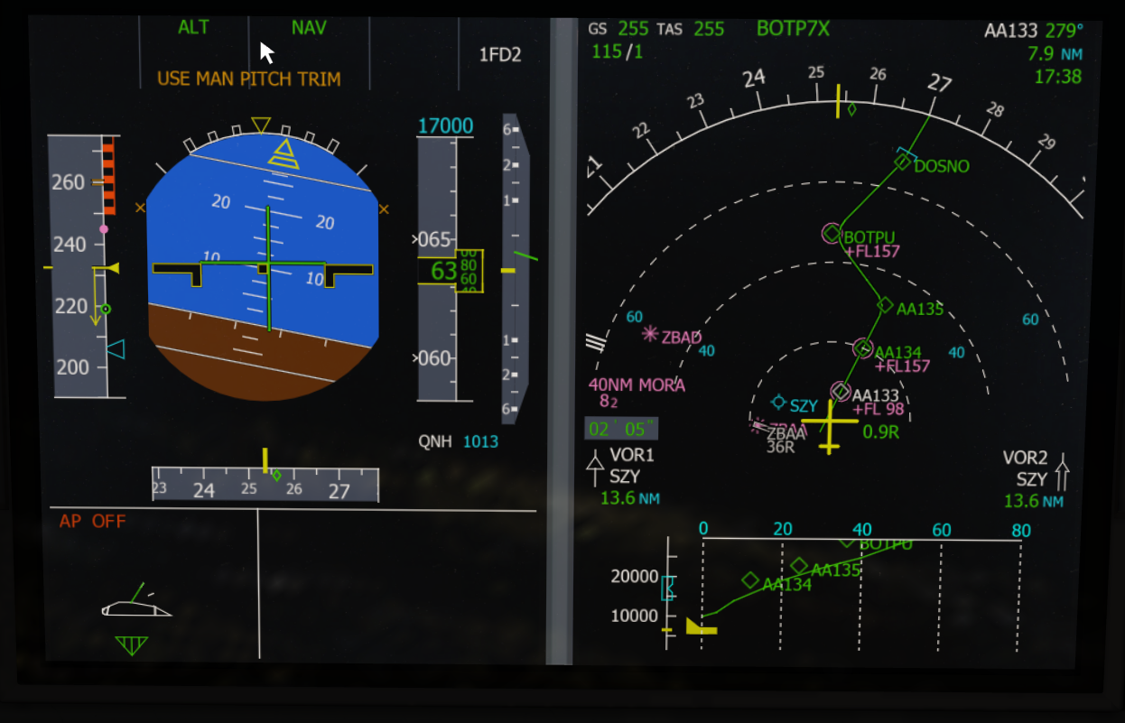
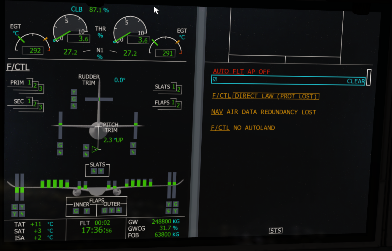
Direct Law provides a much more direct relationship between sidestick input and control-surface command. Normal envelope protections are no longer available, autopilot and autoland are unavailable, and the pilot must manage pitch attitude, bank angle and trim more manually.
The mod represents this with the DIRECT LAW (PROT LOST) ECAM message, autopilot disconnect and the USE MAN PITCH TRIM indication on the PFD.
Backup Control Law
If all three PRIMs and all three SECs are offline, the Backup Control Module provides a separate last-resort control path. Only limited pitch and roll authority remain, using a reduced selection of surfaces and no normal protections or autopilot functions.
Electrical Power, Batteries and Buses
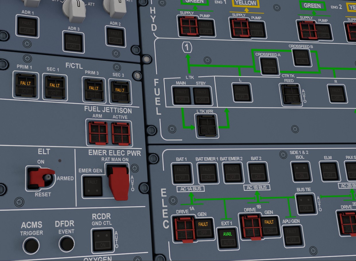
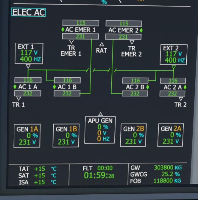
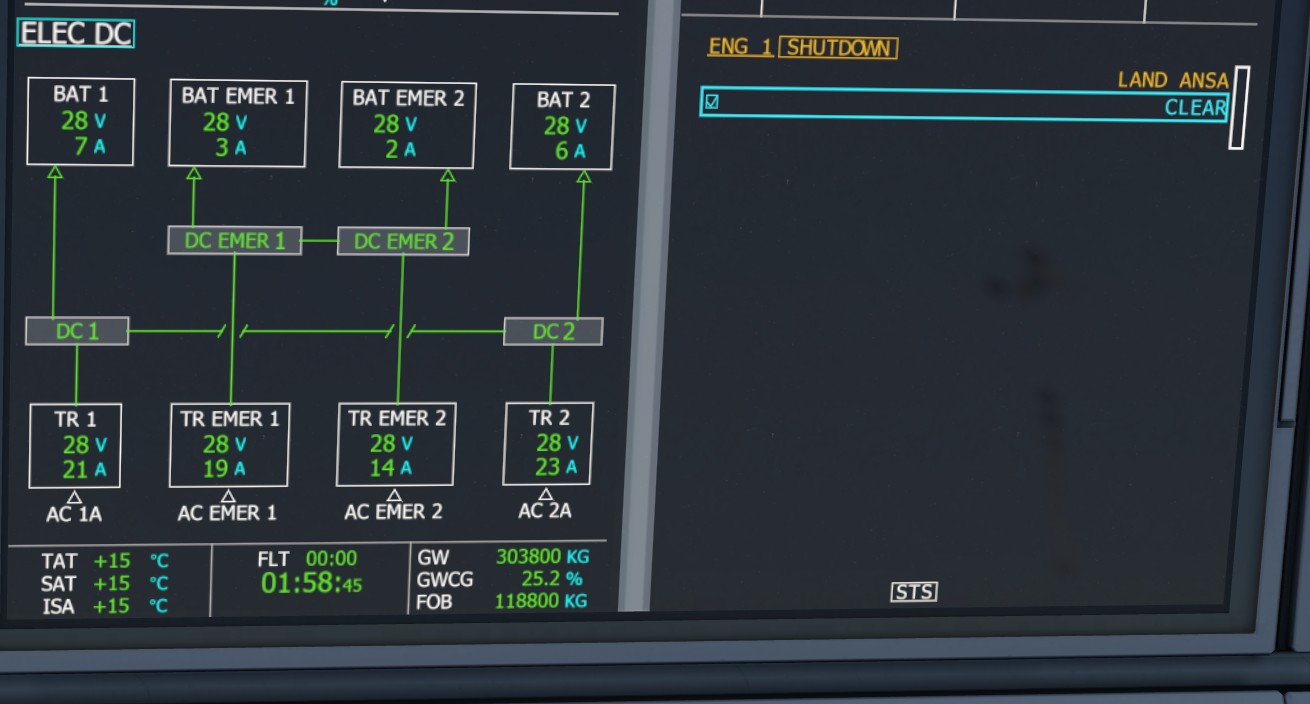
Engine generators, APU generation, external power, batteries, transformer rectifiers and emergency supply are connected so changes of source, battery loading and bus failures produce visible downstream consequences.
Battery-only Operation
Cockpit loads reduce battery state. An unsupported APU start creates extra demand before generator takeover.
Emergency Configuration
Major generation loss produces a reduced essential-services configuration rather than restoring the entire normal network.
Source Transfer
External power, engine generators and APU generation change the active supply path. Battery loading reduces when a generator source takes over, while bus faults remove the systems supplied by that network.
Ground Power Logic
The external ground cart is limited to suitable ground conditions and disconnects automatically when both engines are operating.
Fuel Storage, Transfer and Consumption
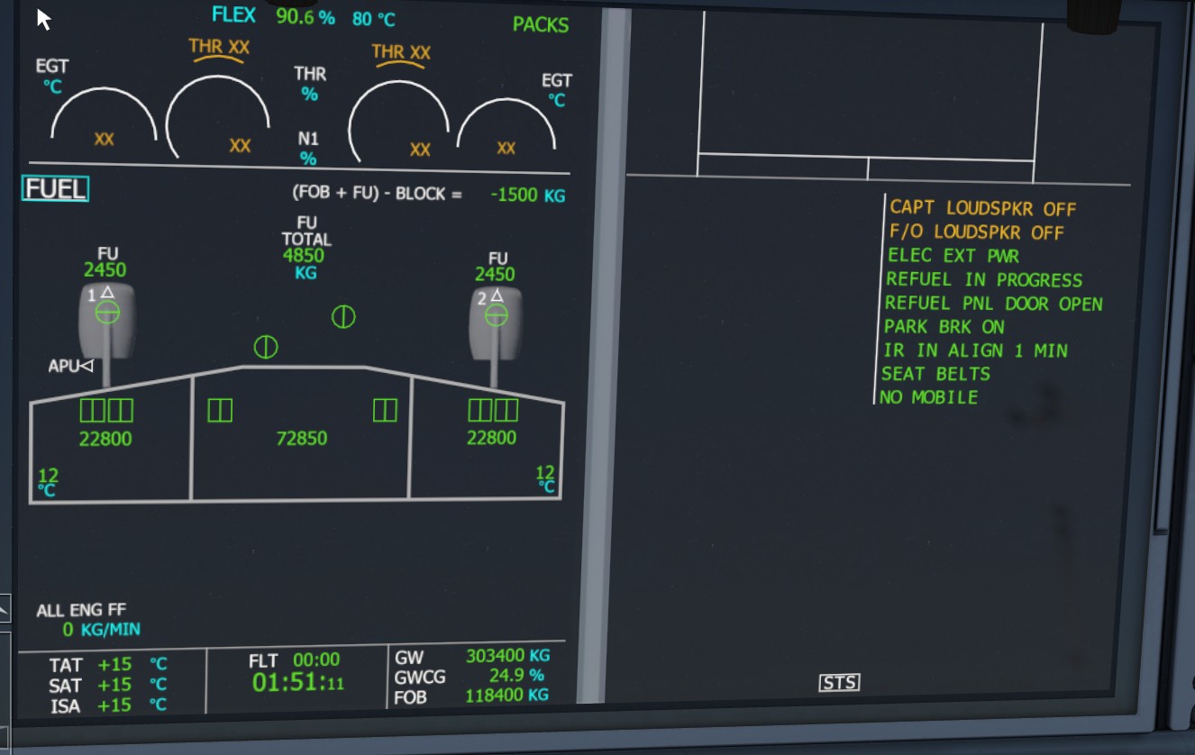
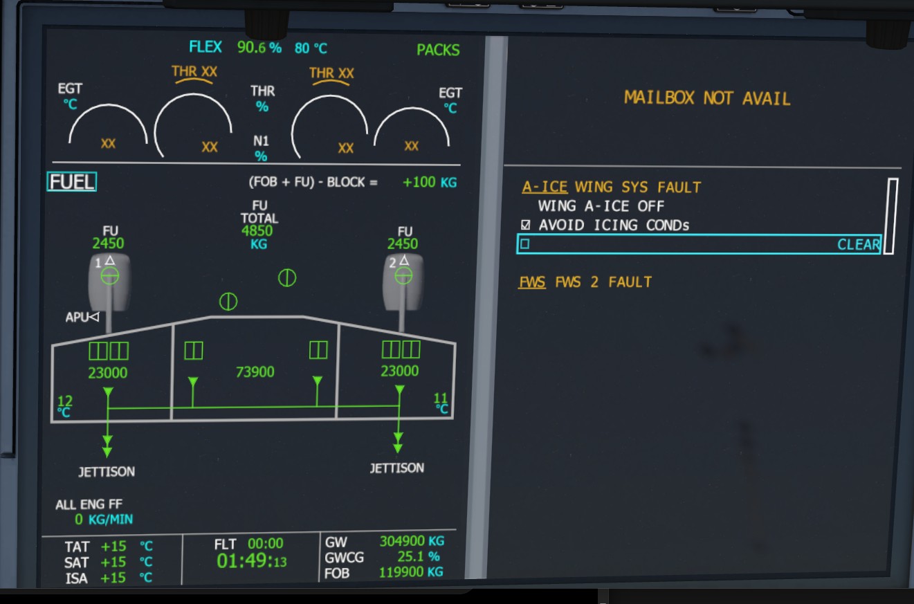
Separate centre, left and right tanks support centre-first burn, wing feed, APU use, refuelling and fuel jettison.
Tank Logic
Fuel is removed from individual tanks and kept synchronised with aircraft weight and fuel-on-board indications.
APU Demand
Electrical load, bleed-air use and ECON mode change APU fuel consumption.
Fuel Temperature and Cold Soak
Centre and wing-tank temperatures change gradually with the aircraft’s environment. Fuel cools during extended high-altitude operation, remains cold after descent and landing, and then warms progressively on the ground.
Refuelling Distribution
Refuelling adds fuel through the separate tank model rather than instantly changing one total value. Centre and wing quantities remain synchronised with fuel-on-board and aircraft weight.
Fuel Leaks and Abnormal Loss
Selectable leak scenarios remove actual fuel from the affected side and can be triggered by altitude or scenario logic. Tank quantities, fuel-on-board and aircraft weight continue to follow the loss.
Flight-plan Fuel Integration
Block-fuel and fuel-used values are linked to the simulated tank state so the cockpit fuel plan and physical fuel quantity remain aligned as closely as the simulator permits.
FMS and MCDU Fuel Entry
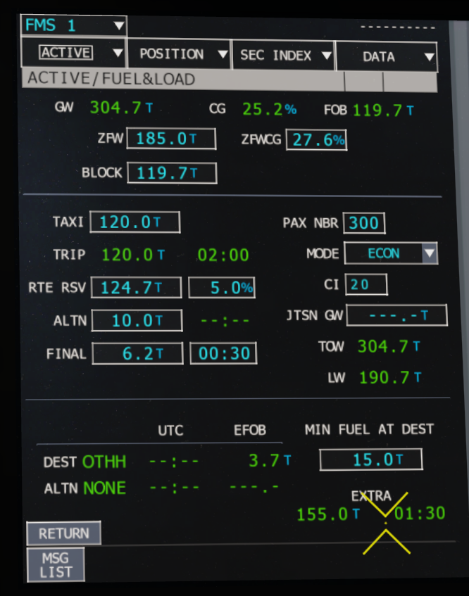
The Multi-Function Control and Display Unit provides the ACTIVE/FUEL&LOAD page used to enter the fuel plan and review the resulting aircraft weights.
BLOCK and TAXI Workflow
BLOCK is entered as the planned total fuel load. In the Advanced Mod workflow, trip fuel plus taxi fuel is entered in the TAXI field so the fuel plan and calculated values remain aligned with the mod’s refuelling logic.
Calculated Aircraft Weights
The entered fuel and load data is used to derive gross weight, take-off weight and landing weight. These values update as fuel is loaded, burned or jettisoned.
Clean and Configuration Speeds
Weight-dependent clean speeds and flap/slat limits are calculated from the active aircraft condition rather than remaining fixed values, helping the displayed speeds follow the current fuel and loading state.
APU, Bleed Air, Air Conditioning and Cargo Temperatures
Updated 3 August 2026: This chapter now includes dynamic engine bleed-air output, cockpit and cabin temperature zones, forward cargo conditioning and bulk cargo heating.
The APU provides electrical and pneumatic power with start loading, generator takeover, demand-sensitive bleed supply, ECON behaviour, ground-cart logic and airborne shutdown scenarios.
Ground Services
The ground cart connects only under suitable ground conditions and disconnects automatically once both engines are running.
Bleed and ECON
APU bleed demand increases fuel use and provides pneumatic supply for the packs on the ground. ECON reduces both consumption and available pneumatic output.
Airborne Shutdown and Restart Inhibition
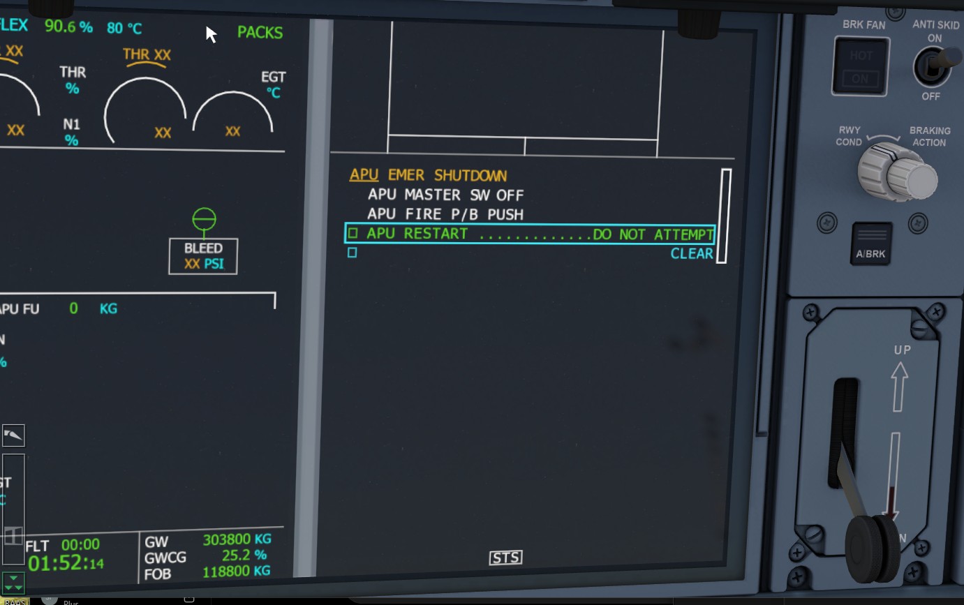
Selected scenarios can command an airborne APU emergency shutdown, generate the associated ECAM procedure and inhibit an attempted restart when the failure remains active.
Demand-sensitive Fuel Use
Electrical generation and bleed-air demand increase APU fuel consumption, while ECON mode reduces fuel use together with available pneumatic output.
Continuation of APU and bleed-air chapter
REAL A350ADVANCED MODSIMULATOR LIMITATIONAir Conditioning, Cabin and Cargo Temperatures
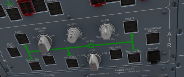
The environmental system now treats cockpit, cabin and cargo temperatures as changing aircraft conditions rather than fixed indications. Temperature responds gradually to the selected controls, ambient conditions and the pneumatic energy available from the APU or operating engines.
Cockpit and Cabin Zones
The cockpit and cabin selectors command separate temperature targets. Each zone warms or cools progressively, so changing a selector does not produce an immediate temperature jump.
Forward Cargo Compartment
The forward cargo compartment follows its selected temperature demand and reacts over time to available conditioned air and outside temperature. It can therefore remain noticeably colder or warmer than the occupied zones.
Bulk Cargo Heating
The bulk compartment uses its own temperature selector and heater logic. A higher setting can maintain a warmer compartment for temperature-sensitive loads such as live animals; placing the selector at the minimum setting leaves the heater effectively inactive.
Dynamic Engine Bleed Air
Bleed-air heating from the engines is dynamic. Available pack heating varies with engine operation and pneumatic output instead of acting as a simple permanent on/off heat source, giving stronger response when more bleed energy is available and a slower response at low supply.
APU and Ground Operation
With the engines shut down, APU bleed can supply the packs and begin moving the selected zones toward their targets. Without an active pneumatic source, temperatures are influenced more strongly by the outside environment.
Thermal Inertia
Cabin and cargo spaces retain heat or cold and continue to change gradually. Hot-soak and cold-soak conditions therefore take time to correct, particularly during extended ground operation.
Engine Oil and Condition
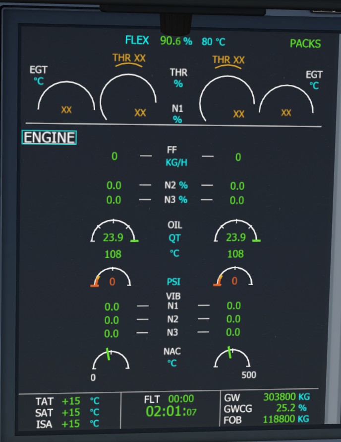
Each Trent XWB has persistent oil quantity that reduces with use and can trigger low-quantity and pressure indications.
Persistent Condition
Oil is no longer a fixed static value.
Maintenance
The Advanced interface restores oil quantity and normal service condition.
Engine Vibration and Condition
Engine vibration and abnormal-condition indications can accompany selected engine scenarios, giving faults a visible and operational effect beyond a single ECAM message.
Phase-of-flight Engine Failures
Checkride and failure overlays can introduce engine events during start, take-off, cruise, descent or final approach, depending on the selected scenario.
Fire, Smoke and Cargo Protection
Engine, APU, cargo, avionics and lavatory scenarios can generate warning audio, ECAM alerts, isolation actions, agent discharge and LAND ASAP consequences.
Fire Detection
Fire-test and failure logic drives master warning, fire indications and extinguisher actions.
Smoke Scenarios
Forward/aft cargo, avionics and lavatory smoke can be timed or scenario-driven and may isolate ventilation.
Cargo Ventilation and Agent Consequences
Cargo-smoke scenarios isolate ventilation, support extinguisher-agent actions and can retain smoke indications during discharge, reproducing the operational need to land as soon as practical.
Ground and Airborne Scenario Control
Timed smoke and fire events can be inhibited or armed according to the selected scenario and phase of flight, preventing inappropriate triggers during setup.
ECAM, STATUS and Memos
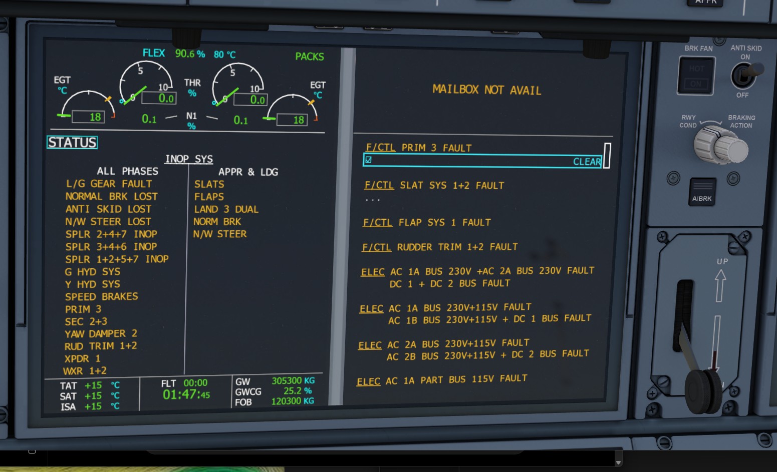
Messages are tied to system state, so clearing an alert does not magically restore failed equipment.
Added Messages
Hydraulics, brakes, accumulator, PRIM/SEC, spoilers, oil, APU, navigation, leaks, smoke and approach information.
Status Consequences
Longer-term degradation remains visible for the rest of the flight.
Approach and Landing Information
Approach and landing memos can reflect degraded flaps, slats, braking, steering and hydraulic availability so the landing configuration matches the actual aircraft state.
Persistent System State
Warnings may be cleared from the active ECAM stack while the underlying failure remains visible on STATUS and continues to affect the aircraft.
ROW/ROP, RAAS and QAR
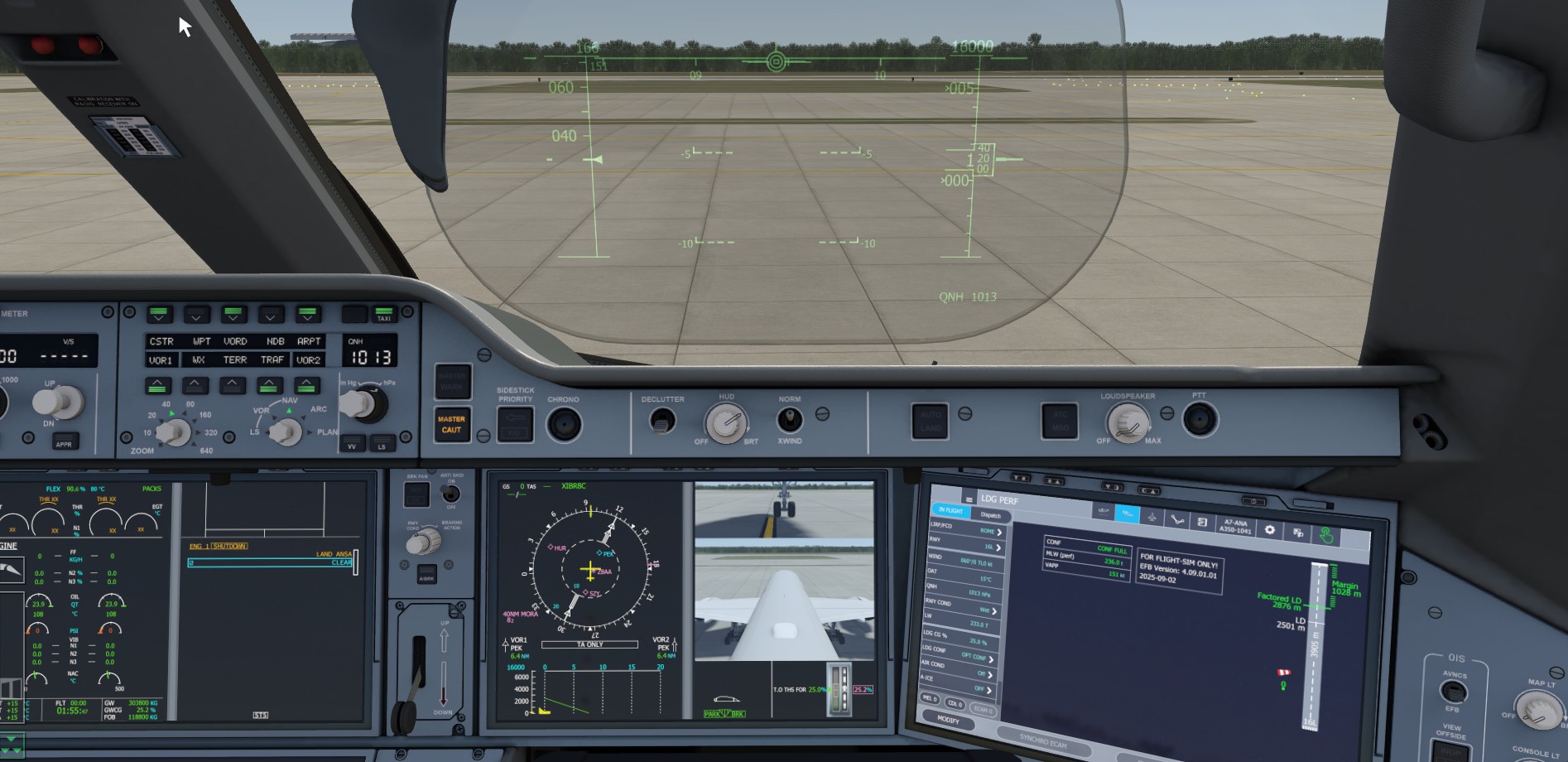
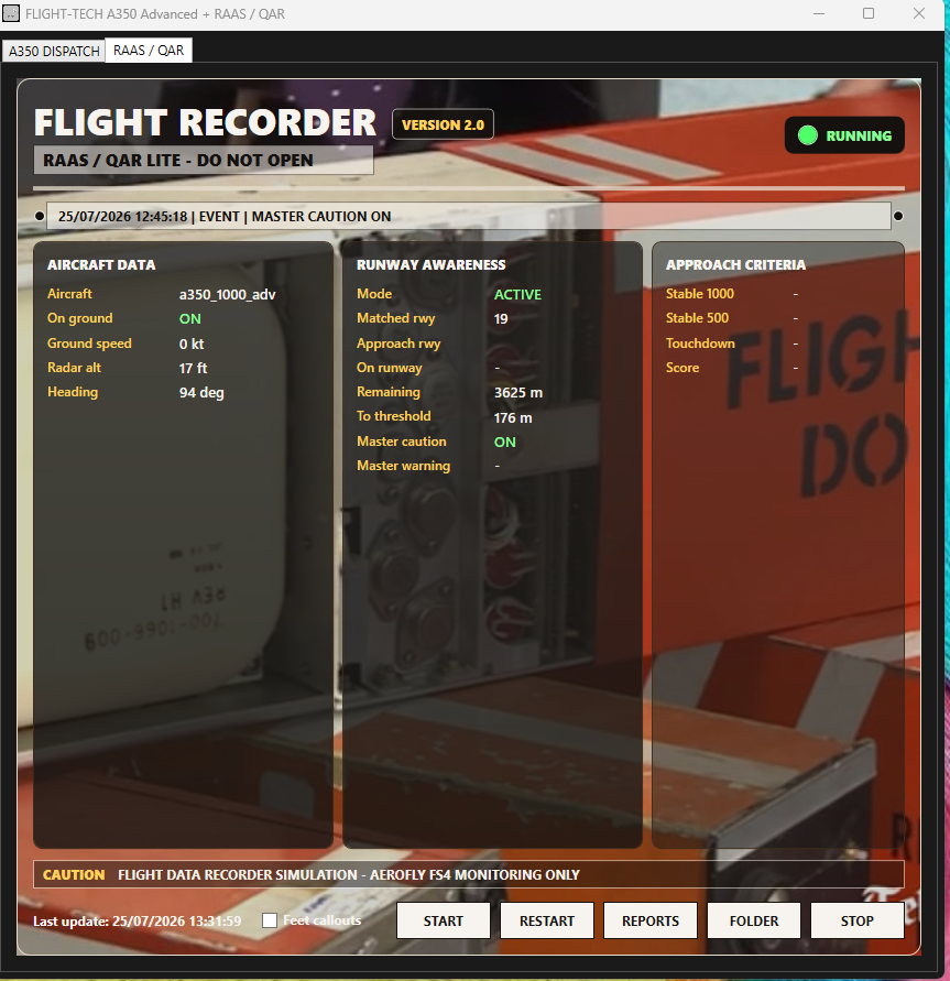
Runway geometry, stopping performance and aircraft state drive RWY TOO SHORT, MAX BRAKING MAX REVERSE, runway-awareness calls and recorded approach events through the integrated RAAS/QAR system.
Runway Protection
Take-off and landing logic are separated to prevent phase-inappropriate warnings.
Recording
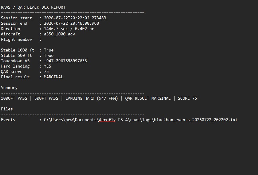
QAR events can capture unstable approach, hard landing, rejected take-off and runway information.
Post-flight Report
The QAR report combines stable-approach checks, touchdown vertical speed, hard-landing assessment, score and final result, with the detailed events file retained for investigation.
Landing Distance and Degraded Braking
The usable runway changes with touchdown position and aircraft condition. A brake, hydraulic, anti-skid or tyre fault can turn an otherwise acceptable runway into an overrun risk.
Available Runway
RAAS uses the matched runway threshold, runway end and live aircraft position to calculate the distance remaining. The panel displays this value in metres; optional voice calls may use feet.
Long Landing
Touchdown beyond the configured touchdown zone reduces the physical stopping distance and can trigger a long-landing event. The event is recorded at touchdown rather than being inferred later during rollout.
Fault-adjusted Stopping Capability
Normal-brake loss, Yellow-system degradation, anti-skid loss, accumulator depletion and tyre damage reduce the available deceleration or protection and therefore increase the operational runway requirement.
Warnings and Action
RWY TOO SHORT warns that the calculated stopping requirement exceeds the runway available. MAX BRAKING MAX REVERSE calls for the maximum available stopping action after landing.
Operational Interpretation
Do not treat the runway-length figure as a fixed answer. First determine which braking mode remains available, whether anti-skid is operating and how much accumulator pressure is stored. Then consider the touchdown point and the live runway remaining. RAAS and ROW/ROP support that decision; they do not restore lost braking capability.
Tyres, Brakes and Hard Landings
Brake temperature, landing rate, wheel loading and configuration exceedances can create persistent damage, tyre-pressure warnings, degraded braking, ground vibration and maintenance consequences.
Brake Starting Condition
Load cold, turnaround-warm, hot or randomly heated brakes so brake temperature forms part of the aircraft’s starting condition.
Hard-landing Damage
Excessive touchdown rate and wheel loading can produce persistent tyre or wheel damage, brake indications, abnormal rollout vibration and a maintenance requirement.
Flap and Slat Overspeed
Exceeding configuration speed limits can trigger latched flap or slat system faults, ECAM and STATUS consequences, approach limitations and maintenance action.
QAR and Maintenance Record
Severe landings and configuration exceedances can be recorded as flight events and carried into the aircraft maintenance state rather than disappearing after the warning is cleared.
Tyre-pressure and Vibration Effects
Severe touchdown loads can produce tyre-pressure loss and a low-frequency ground vibration during taxi or rollout, making the damage physically noticeable.
Persistent Aircraft Condition
Hard-landing and configuration-exceedance damage can remain active until maintenance action is completed through the Advanced Panel.
Advanced Interface and Maintenance
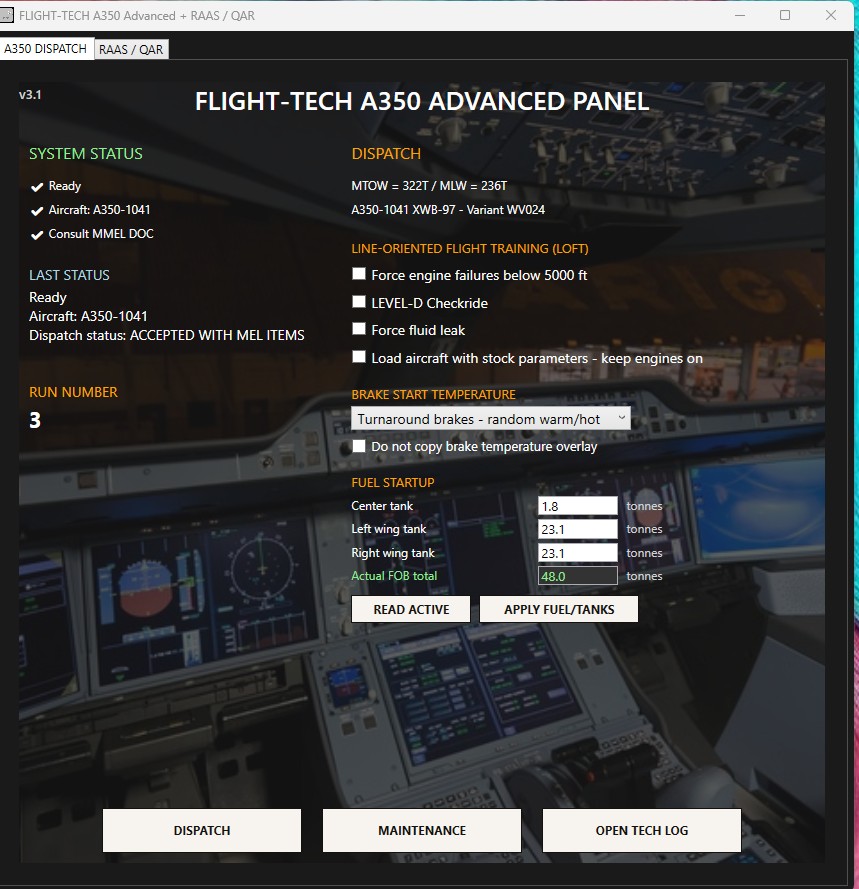
The combined FLIGHT-TECH interface prepares aircraft state, fuel, brake condition, failures, maintenance and Level-D-style checkrides, while providing direct access to the integrated RAAS/QAR recorder.
Dispatch and Configuration
Select fuel distribution, starting brake temperature, stock or Advanced aircraft state, fluid-leak scenarios and checkride options before loading the simulator.
Maintenance and Technical Log
Review dispatch condition, restore serviceable systems and open the technical log so persistent faults and maintenance actions remain part of the operating workflow.
RAAS Runway Awareness
The integrated recorder uses live aircraft and runway geometry data to identify the matched runway, monitor runway remaining and track master cautions or warnings.
QAR Approach Monitoring
Stable-approach gates, touchdown performance and selected flight events are logged for later review through the reports and event-recording functions.
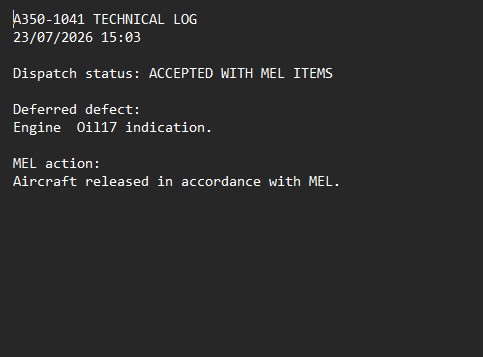
Deferred Defect Record
Accepted MEL items, deferred defects and release action are written to the technical log so the selected dispatch condition can be reviewed outside the simulator.
MMEL-style Dispatch
The dispatch workflow can release the aircraft with selected deferred defects, record the MEL action and preserve the accepted-with-items status in the technical log.
Aircraft-state Variants
Engines-off, engines-running, normal and maintenance variants are managed as complete aircraft states so the selected configuration is applied consistently before loading.
Sound and Environmental Effects
Ground roll, touchdown, cabin movement, wind, braking rumble and electrical ambience add physical weight to each phase of flight.
Beta Integration
Newer engine and flap audio is retained.
Advanced Effects
Earlier strong touchdown and ground-roll effects are selectively restored and expanded.
Known Limitations
A350 Advanced works within variables exposed by Aerofly FS 4. Some real-aircraft architecture is therefore approximated to reproduce the operational consequence as closely as practical, including simplified bus topology, Flight-Control Law transitions, fluid loss, fire-agent behaviour and component reset logic.
Additional Behaviours Represented Across the Mod
- Centre-first fuel burn, wing feed, refuelling, jettison, APU demand and fuel cold soak.
- Green/Yellow hydraulic dependencies, normal/alternate/accumulator braking and steering loss.
- PRIM/SEC reboot logic, spoiler allocation, BCM backup control, retained trim, rudder-trim and yaw-damper loss.
- Battery loading, generator takeover, ground power and emergency electrical configuration.
- Engine oil consumption, vibration, phase-of-flight failures and maintenance restoration.
- Smoke, fire, cargo ventilation, pressurisation, ADIRS, GPS and avionics failures.
- Hard-landing damage, flap/slat overspeed, tyre vibration and persistent maintenance state.
- ROW/ROP, RAAS runway geometry, long-landing monitoring and QAR post-flight reports.
- Dynamic cockpit, cabin and cargo temperature behaviour with APU and engine bleed-air dependencies.
Images: A350 first flight by Don-vip (CC BY-SA 3.0); A350 cockpit by João Carlos Medau (CC BY 2.0); landing gear and Trent XWB by Julian Herzog (CC BY 4.0). Images are cropped/darkened for layout. Aerofly FS 4 screenshots are original captures supplied by the A350 Advanced project and may be used throughout this website.